3D Rendering with Ray Marching レイマーチングによる3Dレンダリング
To render a 3D scene using ray marching, we need to shoot a ray for each pixel. Remember how projection works. By selecting a point on the screen (a pixel), and drawing a ray from the viewpoint, we can determine if it hits an object and decide what should be drawn on that pixel. Using a shader, we can process all the pixels in parallel to complete the whole image.
3Dシーンをレンダリングするには、それぞれのピクセルに対してレイを飛ばす必要があります。プロジェクションの原理を思い出してください。画面上の点(ピクセル)を選んで視点からレイを伸ばし、物体に当たるかどうかを判定してそのピクセルに何を描くかを決めます。シェーダーを使うと、すべてのピクセルを並列に処理して全体のイメージを完成させることができます。
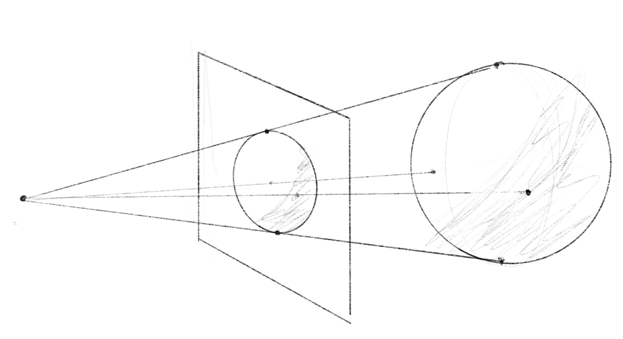
The following example demonstrates the idea. The starting position of the ray and the direction are determined by the viewpoint (eye) and the position of the current pixel (crd).
下のデモでこのアイデアを実演します。レイの始点と方向は、視点(eye)と現在のピクセルの位置(crd)によって決まります。
vec3 eye = vec3(0.0, 0.0, -2.5);
vec3 rayDir = normalize(vec3(crd, 0.0) - eye);
The raymarch function is the main part of this demo, in which we move a point along the ray and use the SDF (signed distance function) to check if it gets close enough to the surface. The function returns the distance if it goes below the threshold, or -1.0 otherwise.
raymarch関数がこのデモのメインで、点をレイに沿って移動させ、SDF(符号付き距離関数)を使って、表面に十分に近づいたかをチェックします。この関数は、距離が閾値を下回る場合その値を返し、それ以外の場合は-1.0を返します。
float raymarch(vec3 eye, vec3 rayDir) {
float dist = 0.0;
float threshold = 0.005;
for(int i = 0 ; i < 16 ; ++i) {
float d = SDF(eye + rayDir * dist);
if(d < threshold) { return dist; }
dist += d;
}
return -1.0;
}
On the dark gray background, the shader only turns the pixel white if the ray intersects with the sphere.
シェーダーは暗いグレーの背景の上で、レイが球体と交差する場合にだけピクセルを白くします。
Finding the normal
法線を見つける
This is a great step. However, the sphere looks flat because it lacks any shading. To make it look more realistic, we need to determine the direction of the surface (normal) and the light source for each point we are rendering. We discussed different ways of modeling lighting in Illuminating Object. So let’s focus on how to find these factors needed to compute the lighting.
素晴らしい一歩ですが、球体は影がないために平らに見えます。よりリアルに見せるためには、レンダリングする各点について、表面の向き(法線)と光源の向きを求める必要があります。「物体を照らす 」で様々なライティングモデルについて触れました。ここではライティングに必要な要素を計算するための方法に焦点を当てましょう。
Finding the direction of the light source is rather straight forward because with the ray marching, we can easily find the position of the surface where it intersects with the ray.
レイマーチングではレイと表面が交差する位置を簡単に求められるので、光源の方向を見つけるのは比較的簡単です。
vec3 P = eye + rayDir * dist;
If the light source can be seen as a point light, like a small light bulb, we can find the direction by subtracting the position on the surface from the position of the light and normalizing the vector. Or, if the light source is far away, like the sun, we can assume that the light direction remains the same regardless of its position.
小さな電球のように光源を点光源として見做して良い場合、光源の位置から表面の位置を引き、ベクトルを正規化することで方向を求められます。また、太陽のように遠くにある場合は、光の方向が位置に関係なく変わらないと仮定することができます。
To find the normal, we can use numeric approximation method for the gradient. In other words, by comparing the return values of the SDF for the neighboring points along each axis, we can determine the direction in which the distance increases the most. This direction corresponds to the direction in which the surface is facing.
法線を求めるには、勾配の数値的な近似が使えます。つまり、それぞれの軸の上で隣り合う点のSDFの戻り値を比較することによって、距離が最も増加する向きを求めることができます。これは表面の向きに対応しています。
vec3 getNormal(vec3 P) {
	vec3 N;
	vec2 h = vec2(0.001, 0.0);
	N.x	= SDF(P + h.xyy) - SDF(P - h.xyy);
	N.y	= SDF(P + h.yxy) - SDF(P - h.yxy);
	N.z	= SDF(P + h.yyx) - SDF(P - h.yyx);
	return normalize(N);
}
The demo below calculates Lambertian reflectance using the normal and the direction of the light. You can change the position of the light source by moving the mouse on the canvas.
このデモでは、法線と光の向きを使ってランバート反射を計算します。キャンバス上でマウスを移動すると光源の位置を変更することができます。
Moving the shape
形を動かす
It’s not very interesting to keep staring at a static scene. Let’s learn how to move the shape around. In this section, we will use a box shape to provide a clear perspective of the shape from different angles.
変化のないシーンを見つめていてもあまり面白くないので、形を動かす方法を学びましょう。異なる角度から形を見ていることが分かりやすいように直方体を使います。
float sdBox( vec3 p, vec3 b )
{
  vec3 q = abs(p) - b;
  return length(max(q,0.0)) + min(max(q.x,max(q.y,q.z)),0.0);
}
There is an amazing YouTube video by Inigo Quilez that explains how this SDF works.
To translate an object, you can simply add a vector to the position. For rotating, we could use a 2D rotation matrix, but we will use this function based on Rodrigues’ rotation formula, which gives the rotated vector of an original vector around the axis by an angle .
位置にあるベクトルを足すだけで物体を移動させることができます。回転には、2D回転行列を使用することもできますが、ここではRodriguesの回転公式に基づいたこの関数を使います。この公式は、元のベクトルのを軸を中心に角度だけ回転したベクトル、を返してくれます。
vec3 rotate(vec3 p, float angle, vec3 axis) {
	float s = sin(angle);
	float c = cos(angle);
	float oc = 1.0 - c;
	vec3 n = normalize(axis);
	return p * c + cross(n, p) * s + n * dot(n, p) * oc;
}
You may have noticed that the demo code appears to be moving the position of the ray instead of the object. Your intuition is correct. Since positions are relative, moving the ray is equivalent to moving the object.
デモのコードは物体の位置ではなくレイを動かしているように見えるかもしれません。これはその通りで、位置というのは相対的なものなので、レイを移動するのはオブジェクトを移動することと同じです。
float SDF(vec3 p) {
	p += vec3(sin(time * PI) * 0.2, 0.0, 0.0); // translation
	p = rotate(p, time * PI, vec3(1.0)); // rotation
	return sdBox(p, vec3(0.2, 0.15, 0.1));
}
The demo below visualizes the output of the SDF function by slicing the space at z = 0. Faint stripes are added to the gradient to make it easier to see the distance. As the object moves and rotates, the distance to the object changes accordingly.
下のデモでは、 SDF関数の出力をz = 0で空間を輪切りにして見せています。距離を見やすくするために、グラデーションに薄いストライプを追加しました。物体が移動、回転すると、物体までの距離もそれに応じて変化します。
Placing multiple objects
複数の物体を配置する
You can place multiple objects in the scene by taking the minimum value of their SDFs. Let’s examine this concept in a 2D slice first. Look closely at what this operation does to the gradient of the distance. You might also notice how the shapes seamlessly merge together when they overlap. We will explore this further when discussing boolean operations of shapes.
複数の物体をシーンに置くには、それらのSDFの最小値を取ります。まずは2Dスライスで見てみましょう。この操作が距離のグラデーションに対して何をするのかに注目してください。物体が重なると形がシームレスに融合することにも気づいたかもしれません。これについては、形状のブール演算について説明する際に詳しく説明します。
float SDF(vec3 p) {
	float d = sin(time * PI / 3.0) * 0.125 + 0.25;
	return min(sdOctahedron(p - vec3(d, 0.0, 0.0), 0.2), sdSphere(p + vec3(d, 0.0, 0.0), 0.2));
}
Here is the 3D rendering with Ray Marching. To assign different colors to objects, you can compare the distances to the objects to find which object the ray has hit.
下はレイマーチングによる3Dレンダリングの例です。物体に異なる色を割り当てるには、レイからそれぞれの物体までの距離を比較して、どちらの物体にレイが当たったかを調べます。
vec3 baseColor = sdSphere(P, 0.2) < sdOctahedron(P, 0.2) ? vec3(0.3, 0.6, 1.0) : vec3(1.0, 0.4, 0.5);
Drawing shadows
影を描く
Did you feel that something was still off in the last example? It looks a little strange when two objects get closer because there is no shadow that they should cast on each other.
上の例はまだ何かおかしくないでしょうか。2つの物体が近づくとき、互いの影があるはずなのに描かれていないためちょっと奇妙に見えます。
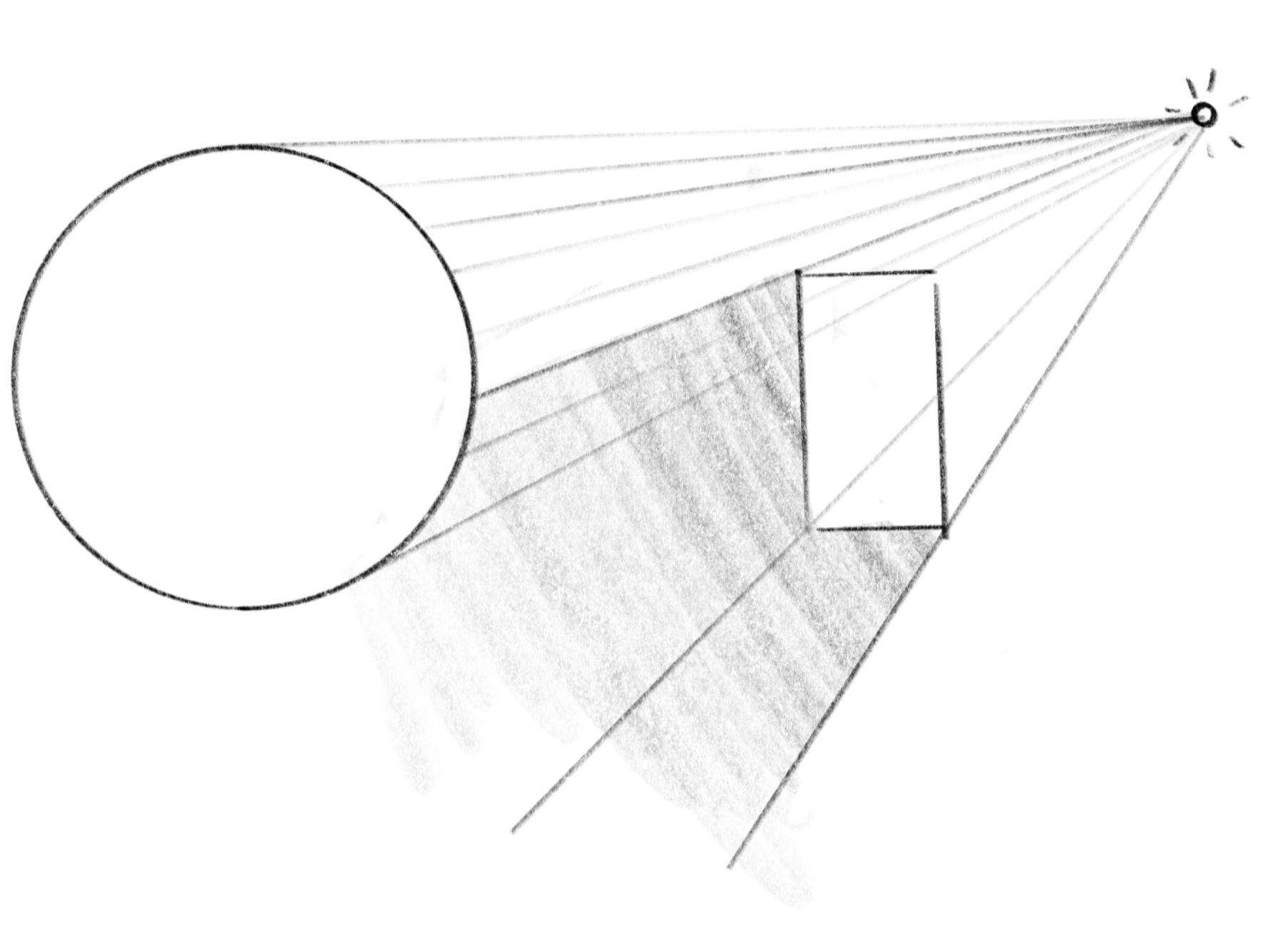
Shadows occur on surfaces where an object blocks the light from a light source. If you draw a line from a point to the light source and the line intersects an object, then the point is behind the object as seen from the source. To check this, you can cast an additional ray to the light source from the point where the ray from the viewpoint intersects an object.
表面に影が生じるのは、物体が光源からの光を遮る場合です。ある点から光源への線を引き、その線が物体と交差する場合、その点は光源から見て物体の後ろにあります。これをチェックするには、視点からのレイが物体と交差する点から、光源に対して追加のレイを飛ばします。
// Take into account shadows
float shadowDist = raymarch(P + 0.001 * N, L);  // Start slightly above the surface to prevent self-shadowing
float shadow = shadowDist >= 0.0 ? 0.0 : 1.0;
Cd *= shadow;
Parallel Projection
並行投影
Lastly, let’s review the different types of projections. As we have seen on the last page, the only difference between perspective projection and parallel projection is whether we cast the rays from a single viewpoint or parallel to each other. Switching between these models is simply a matter of changing how we set the starting points and directions of rays. Run the demo below to see this in action. You can switch between the two projection models by clicking on the canvas.
最後に、異なる種類の投影について見ていきましょう。前のページで見たように、透視投影と平行投影の唯一の違いは視点からレイを放射するか、互いに平行にするかです。これらのモデルを切り替えるには、光線の始点と向きの設定を変えるだけです。下のデモを実行して実際に確認しましょう。キャンバスをクリックすると、2つの投影モデルを切り替えることができます。
vec3 origin, rayDir;
if (parallel) {
	origin = vec3(crd, -2.0);
} else {
	origin = vec3(0.0, 0.0, -2.0);
}
rayDir = normalize(vec3(crd, 0.0) - origin);
float dist = raymarch(origin, rayDir);