Ray Marching レイマーチング
Ray marching is a technique used in computer graphics to render a 3D scene by casting “rays” from the viewpoint and tracing them by moving points step by step. This method is popular for rendering complex scenes with relatively simple shader code. It is also a great tool for understanding and experimenting with various concepts behind 3D rendering, as shown in the pages on Illuminating objects. You can find numerous more examples of ray marching on websites like Shadertoy.
レイマーチングは、視点からのレイ(半直線、光線)に沿って点を逐次的に移動することで、3Dシーンをレンダリングするコンピュータグラフィックスの技術です。この手法は複雑なシーンを比較的シンプルなシェーダーのコードでレンダリングするためによく用いられます。また、「物体を照らす」ページ のように、3Dレンダリングの背後にある様々な概念の理解や実験のための優れたツールでもあります。Shadertoyなどのウェブサイトには、レイマーチングの例が数多くあります。
To learn about shaders, please read The Book of Shaders.
シェーダーについては、The Book of Shadersを読んでください。
英語のRayには光を含む放射エネルギーの線や数学における反直線などの意味があります。日本語では「レイ」と書くことにします。レイマーチングについて考える時は、ある一点から何かを真っ直ぐに飛ばすイメージで捉えると良いでしょう。
What is ray marching?
レイマーチングとは
We perceive objects by capturing the light that is reflected or refracted by them with our eyes. This means that if we can track the path of light, we should be able to simulate what we see. However, the light that reaches our eyes is only a small fraction of the surroundings. Simulating the light that fills the entire scene is not only unnecessary but also computationally impossible.
人は物体によって反射や屈折された目で光を捉えて、それらを知覚します。ということは、光の経路を追跡できれば、私たちが見ているものをシミュレートすることができるはずです。ところが、周囲の光のうち私たちの目に届くのは、ほんの一部です。シーン全体に溢れる光をシミュレートすることは、無駄なだけでなく、計算的にも不可能です。
Ray marching solves this problem by reversing the direction. Instead of tracing all photons, we shoot rays from a viewpoint, such as an eye or camera. We check if the ray intersects with an object. If it does, we examine the point to determine the color we see in that direction. For instance, we can analyze the direction of light sources from the point to understand how the object’s surface is illuminated. We can also shoot more rays towards the light sources to check if the light is blocked by other objects, allowing us to draw shadows.
レイマーチングは、この問題を逆向きに考えることで解決します。すべての光子を追跡する代わりに、視点(目やカメラなど)からレイを飛ばして物体と交差するかどうかチェックします。交差するならその点を調べて、その向きに何色が見えるかを決めます。例えば、その点から見た光源の方向を調べると、物体の表面がどのように照らされているかが分かります。また、光源に向かってさらにレイを飛ばして、他の物体によって光が遮られているかどうかを調べることで、影を描くこともできます。
The method is called ray “marching” because we move points forward step by step along these rays until they hit the objects or go too far without hitting any. This trick can significantly simplify the algorithm because we don’t have to figure out different ways of detecting intersections for different shapes.
この手法がレイ「マーチング(marching - 行進)」と呼ばれるのは、点をレイに沿って一歩一歩、オブジェクトに当たるか、当たらずに遠くに行きすぎるまで進めるからです。このやり方だと、形状ごとに異なる交差点検出の方法を考える必要がないので、アルゴリズムがとても簡単になります。
SDF (Signed distance functions)
Before shooting rays, we need to understand how to define the shapes of the objects we want to draw. We will use functions called SDF (signed distance functions) for this purpose. SDF functions take a point in space as input and return the distance to the closest point on the surface of the object. It is called “signed” because the function returns a positive value if the point is outside the shape and a negative value if the point is inside the shape. We have already seen a few examples here.
レイを飛ばす前に、まず描画する物体の形を定義する方法を理解しましょう。これには、SDF(signed distance function - 符号付き距離関数)と呼ばれる関数を使用します。SDF関数は、空間内の点を入力として受け取り、物体の表面上の最も近い点までの距離を返します。この関数が「符号付き」と呼ばれるのは、点が形状の外部にある場合は正の値を返し、点が形状の内部にある場合は負の値を返すからです。いくつかの例は既にこのページで紹介しました。
The best resource for finding SDFs for different shapes is Inigo Quilez’s website. We will explore various shapes and different ways to combine them in order to design more complex objects. But, let’s begin by understanding how an SDF works using a sphere as an example.
様々な形状のSDFを見つけるには、Inigo Quilezのウェブサイトが最高です。この後、より複雑な物体を作るために、さまざまな形やそれらを組み合わせる方法について見ていきますが、まずは球を例にしてSDFの仕組みを理解しましょう。
This is the SDF sphere function from Inigo’s website.
これはInigoのウェブサイトからの球のSDF関数です。
float sdSphere( vec3 p, float s )
{
  return length(p)-s;
}
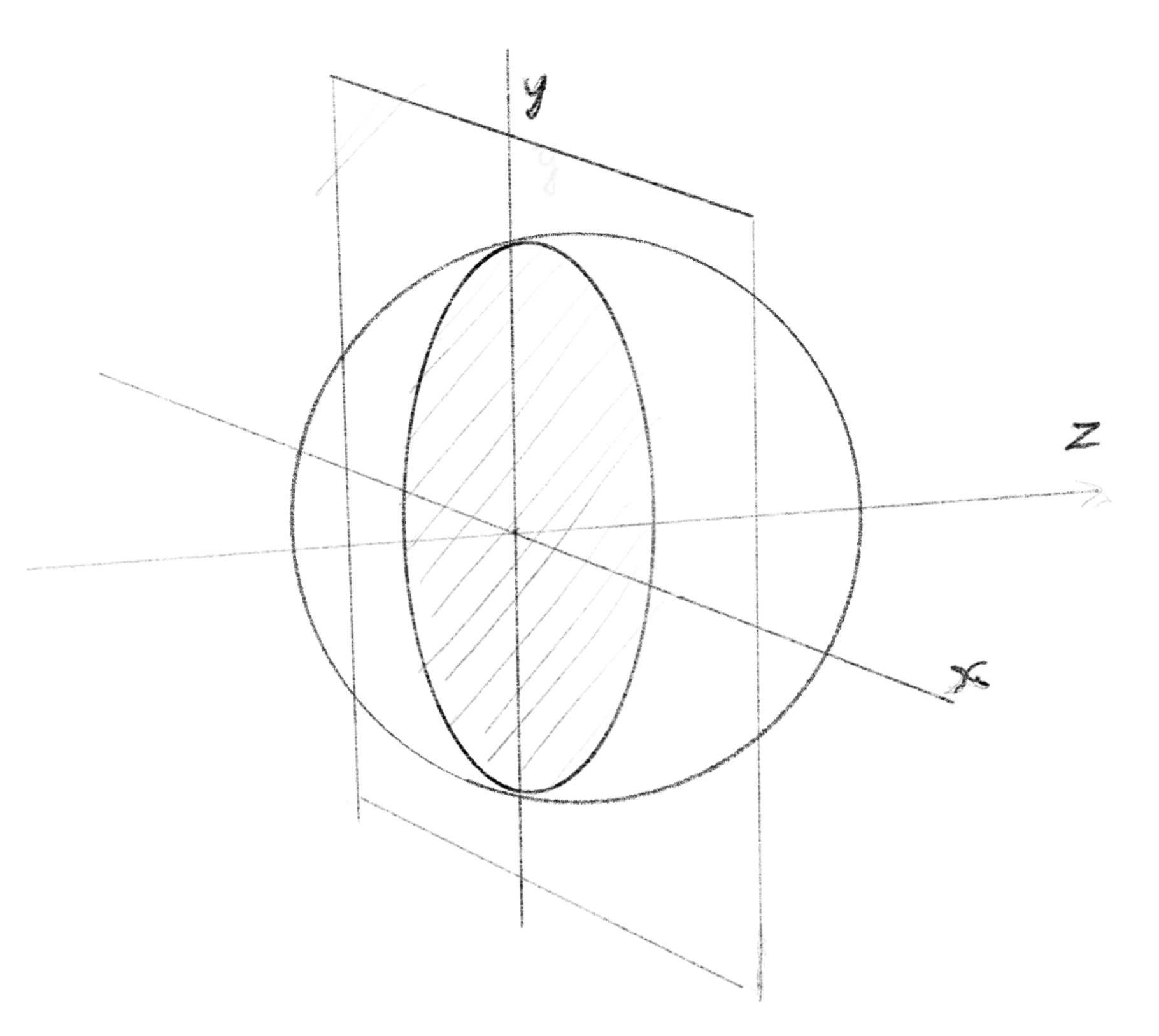
We haven’t made a 3D renderer yet, so let’s render it on a 2D plane by slicing it, like a CT scan. The demo below visualizes the values that this function returns. The center of the canvas corresponds to {x:0, y:0} in the 3D space, and we are slicing a sphere by moving a plane back and forth along the z-axis. The brightness of the pixel represents the return value of the function, meaning that the brighter the pixel, the further it is from the surface of the sphere. Note that inside the sphere, the values are actually negative. The yellow color represents exactly where the surface of the sphere is, where return value is 0. Slicing an SDF in this way is very useful for debugging and visualizing what is going on. We will use this technique through out the rest of the page.
まだ3Dのレンダラーを作っていないので、CTスキャンのように2D平面上でスライスしてレンダリングしましょう。下のデモでは、この関数の返り値を可視化しています。キャンバスの中心を3D空間の {x:0, y:0} に対応させ、球体をz軸に沿って前後に移動することでスライスしています。ピクセルの明るさは、関数の返り値を表していて、ピクセルが明るいほど球の表面から遠いことを意味します。球の内部では実際には値が負になることに注意してください。黄色は球の表面が存在する正確な位置を示し、返り値が0であることを表します。このSDFをスライスする方法は、デバッグや実際に何が起きているのかを目で見て調べるのに非常に便利です。このテクニックはこの先でも使用します。
Let’s see another example. This is an Octahedron.
別の例も見てみましょう。これは正八面体です。
What is great about defining a shape as a signed distance function (SDF) is that it can tell us where the surface is, and it lets us know how far we need to go to reach the surface. This is particularly valuable when moving a point along a ray.
SDFで形を定義することの利点は、表面がどこにあるかと同時に、表面に到達するまでに必要な距離も知れることです。これは点をレイに沿って移動させるために役立ちます。
Casting rays
レイを飛ばす
Now that we have our shapes, we can cast rays. To make it easier to see, the following demo shows this process also in 2D, but from a side view. The horizontal axis is the z-axis, and the vertical axis corresponds to the y-axis in the 3D space. We place a single sphere defined with the SDF from the above, and shoot rays from a view point.
形ができたので、レイを飛ばすことができます。分かりやすいように下のデモでは、このプロセスを横から見た2Dで表示します。水平軸はz軸であり、垂直軸は3D空間のy軸に対応しています。上で見たSDFで定義された球体を一つ配置し、視点からレイを発射します。
In case of perspective projection, all the rays have the same starting position, but different directions. We will march points along these rays. For each ray, we calculate the distance from the point to the closest surface of the object, and move the point for the distance. Think of this as finding a safe distance to advance the point without entering the object. We want to avoid excessive looping, but we also don’t want to perform overly complex calculations for each step. That’s why we defined the shape with SDF, because with an SDF, obtaining the distance is simply a matter of passing the position of the point to the function.
透視投影の場合、レイは全て同じ出発位置と異なる向きを持っています。これらのレイに沿って点を進めていきます。それぞれのレイについて、点から最も近い物体の表面までの距離を計算し、その距離だけ点を移動させます。これは点が物体の中に入り込まずに進める安全な距離を求める方法です。無駄な繰り返しは避けたい一方で、各ステップごとに過度に複雑な計算を行いたくありません。SDFで形を定義したのはそのためで、点の位置を関数に渡すだけで距離を取得できます。
With this method, the distance often doesn’t reach zero. But in practice, if the function (SDF) returns a very small value below a certain threshold, we can assume that the ray intersects with the surface of the object there.
この方法では、距離はゼロに到達しないこともよく起こります。ですが実用上は、関数(SDF)がある閾値以下の非常に小さな値を返す場合、その場所でレイが物体の表面と交差すると見なすことができます。
In this demo, the shape (sphere) is drawn in the shader, while rays are rendered using p5.js drawing functions. This may seem tricky, but note that
sdSpherein JavaScript and GLSL is identical, andnormalizePosToScreenCrdin JS andscreenCrdToNormalizedPosin GLSL are the reverse of each other.
このデモでは、形状(球)をシェーダーで描画し、レイをp5.jsの描画関数でレンダリングしています。ややこしく見えるかもしれませんが、JavaScriptとGLSLのsdSphereが同じで、JSのnormalizePosToScreenCrdとGLSLのscreenCrdToNormalizedPosは互いに逆の操作だということに注目してください。
For parallel projection, we cast the rays in a parallel manner. The rest of the logic can stay exactly the same.
平行投影の場合、レイを平行に飛ばします。他のロジックは全く同じままです。